The best way to test your decimal adder is to feed it all possible
(valid) inputs, and the easiest way to do that is with a counter for as
many bits as you need independent inputs. This paper shows how to cascade
two 4-bit counters to get eight independent inputs. It also shows how to
turn the (binary) Cnt4 built-in macro into a decimal counter,
which does not generate (except possibly in transit) invalid decimal values.
A Cnt4 0 0 0 0 RESET CLKThese four outputs are named A.0 through A.3, and you can trace them in the simulator by the line:
A HEX A.3 A.2 A.1 A.0which gives a single hexadecimal digit in the trace. If you want to see the bits separately, change the HEX line to:
A3210 HEX A.3 0 0 0 A.2 0 0 0 A.1 0 0 0 A.0Adding a second counter based on CLK would only replicate the same outputs. Instead we need to drive the clock input to the second counter with a signal that changes only 1/16th as often as CLK. The most significant bit out of the first counter, A.3 serves this purpose:
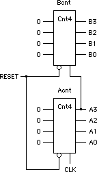
B Cnt4 0 0 0 0 RESET A.3The equivalent circuit diagram for this pair of counters is:

Note that with this circuit, the outputs from counter B will change somewhat later than the outputs from counter A, typically the propagation delay through the counter (two or three gate delays), as shown in this trace fragment:
CR BA #The above trace was obtained with the clock info and trace lines set as follows:
11 0F 164
01 0F 165
01 0F 166
01 0F 167
01 00 168
01 00 169
11 00 170
11 10 171
11 10 172
11 10 173
11 10 174
01 10 175
01 10 176
01 11 177
01 11 178
20,5,2,1 ; run,ClkRate,PonDly,TrateOrdinarily you would set the trace rate (the 4th number on this line) to twice the clock rate (that is, 10 for a clock rate of 5 as shown), in order to see only one trace line for each output value. However it is a good idea to run the trace on every line like this at least once or twice to verify that your circuit is not too slow for your specified clock.
CR HEX CLK 0 0 0 RESET
BA HEX B.3 B.2 B.1 B.0 A.3 A.2 A.1 A.0

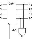
In this counter, when A3 and A0 are both 1 (that is the counter is 1001 or any higher odd number), the gate fires, sending a low to the (low-active) Load control, so the next clock resets the counter to its (all zero) input instead of continuing to count. The GateSim specification for this circuit is the following two lines (each part is one line):
Cnt9 Cnt4 0 0 0 0 is9 CLK
is9 gate Cnt9.0 Cnt9.3
Rev. 2002 October 22